Raspberry Pi Tape Remote (RPTR)
Table of Contents
Introduction
I have known about reel to reel tape for sometime, my Dad has an old 1960’s player in the attic. However it is only relatively recently that I found out that there are some people that still used them for music listening purposes. I think my first real exposure was on the Techmoan YouTube channel, I saw a video about Tips and advice for the Reel-to-Reel buying newbie. Instantly I decided it was a waste of time and money. However the more I thought about it the more I liked the idea of selecting an album or compilation of music, starting the tape and not being able to skip tracks easily. All while seeing the tape player play while listening to the music. The other appealing idea was the retro design and the look of 10 inch tape spools. I continued to think about reel to reel, secretly wanting a player. Till a friend reminded me that people generally spend far more on “ornaments” for their houses than the average cost of a working tape player. This changed my mind, I instantly did an ebay search and found a player that ticked every box: a direct drive so that no belts would need changing, a head that is not prone to wearing out, a model that takes 1/4 inch tape and 10 inch tape reels, touch buttons rather than large mechanical piano key controls, vu meters, a nice 80s black finish and most importantly in working order. To make it even better it was a buy it now auction that was in the neighbouring town. So I bid, won, paid and picked it up the same day!
I’m very pleased with it.


A note on getting 1/4 tape
New tape is hard to find and costly because there are not many companies making tape anymore. I ruled out buying new tape as I’m not completely crazy. New tape is available second hand on eBay. It is called “new old stock” or “NOS”, which is essentially shrink wrapped tape that has not been used yet. The next step down is random tape from “masters”. These are reels of used tape that were once used in some sort of studio. There will be cuts and the amount of tape per reel will vary. There is another form available on ebay which is old consumer tape of varying quality. I stayed away from the latter and managed to find a good deal on ebay for 10 used reals of tape that were discarded from an archive. They were “masters” for an audio book, so had cut marks in and the amount of tape on each reel varies. However all the reels were nice polished aluminium and mostly full. As with audio in general there is a fair amount of snake oil about and I discovered that the type of tape seems to be highly debated. I think I got lucky with the tape, in any case the recordings I have made play back fine and the tape head does not get too messy.
The project
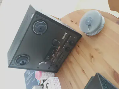
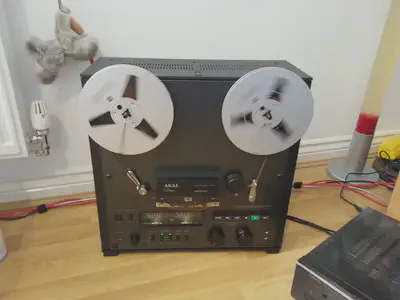
I got an Akai GX-620 reel to reel tape player. While researching the player I found the service manual and read it. Also before I got my player and when I was looking for players I found out that some players including my own had a wired remote control add on. It is a small box that had the normal tape function buttons with a wire that plugs into the back of the tape player. Thus you could control the player from the comfort of the couch without getting up.
This all leads me to this project: Why not connect a Raspberry Pi up to the tape player and remotely control it!
Which is exactly what I did. I made a cable from the tape player to a relay board, connected the relay board to teh GPIO pins on a raspberry pi, connected a usb IR receiver to the Raspberry Pi and wrote a two short python scripts to stick it all together. So now I can control my 20+ year old tape player using my new remote control or mobile phone!
Signaling and Connectors
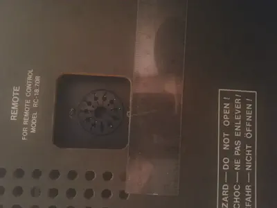
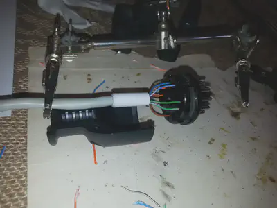
While the project was in it’s inception phase, I started researching how the tape player remote controls work and how I could connect a new cable to the tape player. I found some ebay listings where people have created replacement remote control units and even old remote control units. However I ruled both these options out as they cost too much. However the service manual did have a schematic that had the players circuit diagram. So I was able to understand what sort of circuit to make. If this was a modern device it would use some sort of advanced communication (i2c, 1wire, serial, usb, etc). However this was old. The connector on the back of the player had a number of pins and one was ground. Each of the other pins was related to some tape function (fast forward, stop, play, etc). These functions go in parallel to the function buttons on the unit. So if a function pin was shorted to ground momentarily then it performed that function, just like the actions of the switch on the front of the player. This is great, because a simple relay works.
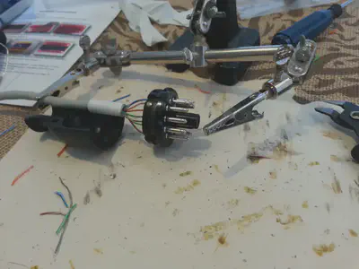
The next step was to find out what the connector on the back of the tape player was. I had never seen anything like it before. The only thing I knew was that it looked like the socket for a vacuum tube. So with a reasonable amount of Google and Internet foo I eventually found out the name of that connector type as “86 Series Connector”. Without this it’s hard to find more information, a producer or supplier. I can only assume that back then there were not many multi connection sockets and plugs that were fine for low voltage non commercial applications. I’m not sure when the DIN series came along, I guess a 6 connector one would do. However the manufactures chose a socket and plug that was actually used for vacuum tubes but it was also available in plug and socket form with nice housing to use. I found out that Farnell listed it in there parts catalogue which also had a copy of the spec sheet for the connectors.
I got one of each of the below (shipped from the US):
Name: COOPER INTERCONNECT 86-3-858 END CAP, THERMOPLASTIC
- Manufacturer Part No 86-3-858
- Farnell Part Number: 1302504
- http://uk.farnell.com/cooper-interconnect/86-3-858/end-cap-thermoplastic/dp/1302504
Name: COOPER INTERCONNECT 86-CP11 PLUG & SOCKET CONNECTOR, PLUG, 11 POSITION
- Manufacturer Part No 86-CP11
- Farnell Part Number: 1311360
- Data Sheet: http://www.farnell.com/datasheets/1658178.
- http://uk.farnell.com/cooper-interconnect/86-cp11/plug-socket-connector-plug-11/dp/1311360


Control Cable
There are 6 functions and one ground, I needed 7 wires in total. Given that Cat5e has 8 wires, I thought it a lovely idea to use Cat5e for the control cable for this project. I wired my cable as follows:
| Tape Player Pin | Function | Cat5e wire colour |
|---|---|---|
| 1 | Fast Forward | white/green |
| 2 | Play | green |
| 3 | N/C | N/A |
| 4 | Rewind | white/blue |
| 5 | Stop | blue |
| 6 | GND (34) | white/orange |
| 7 | Rec | orange |
| 8 | GND (26) | white/brown |
| 9 | N/C | N/A |
| 10 | Pause | brown |
| 11 | N/C | N/A |

GPIO
The Raspberry Pi as a pin block commonly called GPIO. It’s a header that people use to connect other devices to. It’s widely documented, the elinux - Low-level_peripherals wiki page is a good start. The functions range from serial, i2c to general input/output lines that can be set. Most of these pins connect directionally to the System on a Chip CPU. The other thing to be aware of is that only so much power can be drawn from the board.
The tricky part is understanding how to connect the GPIO header to the relay board. There are many guides on this and I found it quite hard to decode them. The GPIO pins can be programmed to be input or output, eg send a high or low signal or detect a hight or low signal. I understand that signals are either 0v or 3.3 volts. So actually actuating the relay’s can be an issue. However I found that I was able to connect directly from the Pi to the relay board without any external power supply. The Pi supplies 5v to the relay board that goes to power the relays.
The other issue I wanted to avoid was giving false signals to the tape player. Lord only know what would happen if say all tape functions were activated at some for a minute while a Raspberry Pi booted. When I Pi turns on the GPIO ports have defaults, some are set to IN and some are set to OUT. I found that reading the information too tricky so instead I took a Pi and booted the latest Rasbian. I then measured the voltage of each ov the GPIO pins to find out what the default was. I wanted to pick GPIO pins that by default were set low (ie 0v). That way then the Pi was turned on it would not activate any relays. Below is a table of my findings. There are 10 Pins that default to 0v. Some of the GPIO pins also have dual functions (SPI) and I didn’t want to clash with these functions. So I picked the 7 gpio pins that were low and one that was high. My plan was the wire the relay in such a way that as soon as it gets power from the Pi the default high on one GPIO cuts the single for all the tape functions.
Relay
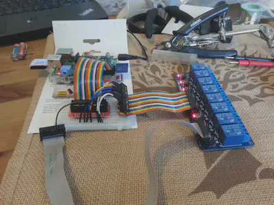
I now had a Raspberry Pi that could control 8 GPIO pins. Given that I have 6 functions, I needed at least 6 relays on a relay board. It seems 4 or 8 seems to be a common number. I got an 8 channel relay board. There seem to be quite a few different types out there for the maker type market, but they all seems to use the same board design. I think I got something similar to: http://www.sunfounder.com/8-channel-5v-relay-shield-module.html.
Initially I wired the Pi to the relay board with wires and a bread board. I then experimented with the setup. They relay board I got has little LEDs on to indicate a relay being on or off. This was very visual and enabled me to get the wiring just right before connecting the tape recorder. Once the wiring was finalised I swapped the wires for a single single ribbon cable from the relay board to the Pi.
Each relay has common, a normally closed and a normally open. I connected the GND of the tape player to to relay 1. I then connected the normally open pin to common on relay 2 to 8. Thus relays 2-8 can have there input high or low or do anything but because the common is disconnected until relay 1 is turned on. Thus when the Pi boots, relay 1 activates, but because all the GPIO ports default to 0v none of the relays activate. Once the Raspberry PI has booted, relay 1 can be turned off, this allows the setting of all the other GPIO ports to be output and low. After this initialisation relay 1 can be turned back on again. I don’t think this was strictly necessary however it does all a little protection and given that there are 2 spare relays, this gives a use for one of them.
| GPIO Pin | Fucntion | Default Rasbian boot Voltage | Relay Pin |
|---|---|---|---|
| 1 | 3.3 | 3v | |
| 2 | 5v | 5v | relay vcc |
| 3 | gpio2 | 3v | |
| 4 | 5v | 5v | relay ry-vcc |
| 5 | gpio3 | 3v | |
| 6 | gnd | 0v | |
| 7 | gpio4 | 3v | relay in1 |
| 8 | gpio14 | 3v | |
| 9 | gnd | 0v | relay gnd |
| 10 | gpio15 | 3v | |
| 11 | gpio17 | 0v | relay in2 |
| 12 | gpio18 | 0v | relay in3 |
| 13 | gpio27 | 0v | relay in8 |
| 14 | gnd | 0v | |
| 15 | gpio22 | 0v | relay in4 |
| 16 | gpio23 | 0v | relay in5 |
| 17 | 3.3 | 3v | |
| 18 | gpio24 | 0v | relay in6 |
| 19 | gpio10 | 0v | |
| 20 | gnd | 0v | |
| 21 | gpio9 | 0v | |
| 22 | gpio25 | 0v | relay in7 |
| 23 | gpio11 | 0v | |
| 24 | gpio8 | 3v | |
| 25 | gnd | 0v | |
| 26 | gpio7 | 3v |
I got most of the information about the above from various places on the web. Here are a list of pages than talk about connecting and using relay boards:
- http://www.susa.net/wordpress/2012/06/raspberry-pi-relay-using-gpio/
- http://www.instructables.com/id/Web-Controlled-8-Channel-Powerstrip/step7/Adding-the-magical-rainbow-wire/
- http://arduino-info.wikispaces.com/ArduinoPower
- http://electronics.stackexchange.com/questions/112730/what-are-the-pins-for-in-this-relay-module
- https://coderwall.com/p/izzsig/driving-a-sainsmart-relay-with-raspberry-pi
- http://www.bitwizard.nl/wiki/index.php/Raspberry_Relay
- https://www.raspberrypi.org/forums/viewtopic.php?t=36225
- https://www.youtube.com/watch?v=oaf_zQcrg7g
Here are a list of pages that talk more about the Raspberry Pi’s GPIO interface:
- http://raspi.tv/2014/rpi-gpio-quick-reference-updated-for-raspberry-pi-b
- http://elinux.org/RPi_Low-level_peripherals
- https://www.raspberrypi.org/documentation/usage/gpio/
- https://www.raspberrypi.org/documentation/configuration/pin-configuration.md
- http://int03.co.uk/blog/2015/01/11/raspberry-pi-gpio-states-at-boot-time/
- http://www.raspberrypi-spy.co.uk/2012/06/simple-guide-to-the-rpi-gpio-header-and-pins/
- https://www.cl.cam.ac.uk/projects/raspberrypi/tutorials/robot/cheat_sheet/
- http://projects.drogon.net/raspberry-pi/wiringpi/the-gpio-utility/
- http://falsinsoft.blogspot.co.uk/2012/11/access-gpio-from-linux-user-space.html
Quick and dirty software
Now that I had a Tape player connected to the relay board and the relay board connected to the Raspberry Pi I needed some way to control it remotely. My Raspberry Pi already had a USB Wifi dongle. I purchased a Flirc USB, trained with with my amplifier remote and connected it to the Raspberry Pi. Thus in theory I could use the remote control to control the tape player.
Initially I used the latest Raspbian image to create a working setup. I decided to code in python to create the software glue to get working. I created two programs: tapecontrol and readkey. Both programs can be added to /etc/rc.local to get started.
The tapecontrol program starts a simple flask web server that routes commands and translates them to send a single to the correct GPIO pin. I chose python and flask as its easy to get started see http://blog.luisrei.com/articles/flaskrest.html for a quick overview of that it can do.
The readkey programs listens for input events from the Flirc and sends them to the tapecontrol server. I separated them so that potentially in the future a better mobile app (read web page) could be developed for mobiles.
Proper software with yocto
While the above software solution works fine. It’s a but hard to build and maintain. And entire Rasbian image is quite large and take a while to boot. While I could provide instructions on how to strip out most of the package or use another cut down Raspberry Pi compatible distribution I wanted something very cut down.
I wanted: Linux + a small libc + busy box + python. I also wanted a sort of fire and forget type approach. In essence I wanted the device to be a lot like an appliance. I don’t want to be able to use that Raspberry Pi for other things. I want it to be more like firmware. A read-only sd card image that boots and just runs the control programs.
I have wanted to try the Yocto Project for a real purpose for some time. It encompasses the Openembedded ecosystem and creates a distribution called Poky. It’s aim is to create disk images from scratch. It’s constructed in such a way that it’s extensible. The idea is to create a tool chain for the target architecture and then build all the components and assemble them into a disk image that is deployed.
Fortunately for me many of the components are already built. The ability to build a distribution comes out of the box. The parts of python I use for GPIO and flask are available. Also the Raspberry Pi target has also been created. So that in theory anyone else can pick up and extend my image. There is extensive documentation available, see the links below for many details:
- http://www.cnx-software.com/2013/07/05/12mb-minimal-image-for-raspberry-pi-using-the-yocto-project/
- https://www.yoctoproject.org/documentation
- https://www.yoctoproject.org/docs/1.0/poky-ref-manual/poky-ref-manual.html#usingpoky-extend-addpkg
- http://git.yoctoproject.org/cgit/cgit.cgi/meta-raspberrypi/tree/README
- https://git.yoctoproject.org/cgit.cgi/poky/plain/meta/classes/icecc.bbclass
- http://stackoverflow.com/questions/14472175/distributed-compile-with-bitbake
- http://layers.openembedded.org/layerindex/branch/master/layers/
- http://www.yoctoproject.org/docs/current/dev-manual/dev-manual.html#usingpoky-extend-customimage-localconf
- http://www.yoctoproject.org/docs/2.1/mega-manual/mega-manual.html
- http://embedonix.com/articles/linux/emulating-raspberry-pi-on-linux/
The bitbake build system is pretty cool so that it does not need to rebuild everything every time. However the first build does take a considerable amount of CPU and disk. It downloads approx 9G of compressed source files and needs about 30G in total to build. It complete in a few hours on my laptop. In theory these are the steps necessary to re-create a sd card image that I use:
sudo apt-get install git sudo screen gawk wget git-core diffstat unzip texinfo gcc-multilib build-essential chrpath socat cpio python python3 python3-pip python3-pexpect xz-utils debianutils iputils-ping libsdl1.2-dev xterm
cd ~
git clone http://git.yoctoproject.org/git/poky -b krogoth
cd poky
git clone http://git.openembedded.org/meta-openembedded -b krogoth
git clone http://git.yoctoproject.org/git/meta-raspberrypi
git clone https://github.com/thomasdstewart/meta-rptr.git
. oe-init-build-env
bitbake-layers add-layer $HOME/poky/meta-openembedded/meta-oe
bitbake-layers add-layer $HOME/poky/meta-openembedded/meta-python
bitbake-layers add-layer $HOME/poky/meta-openembedded/meta-networking
bitbake-layers add-layer $HOME/poky/meta-raspberrypi
bitbake-layers add-layer $HOME/poky/meta-rptr
echo "MACHINE ?= \"raspberrypi\"" >> conf/local.conf
echo "ROOT_PASSWORD = \"password\"" >> conf/local.conf
echo "WIFI_SSID = \"someapssid\"" >> conf/local.conf
echo "WIFI_PSK = \"somepassword\"" >> conf/local.conf
bitbake rpi-rptr-image
While developing this I found it useful to be able to emulate a Raspberry Pi, I did so as follows. (Note that the kernel versions don’t match so kernel modules do load, eg iptables):
wget https://github.com/dhruvvyas90/qemu-rpi-kernel/raw/master/kernel-qemu-4.1.13-jessie
qemu-system-arm -kernel kernel-qemu-4.1.13-jessie -cpu arm1176 -m 256 -M versatilepb -no-reboot -serial stdio -append "root=/dev/sda2 rootfstype=ext4 rw" -hda tmp/deploy/images/raspberrypi/rpi-rptr-image-raspberrypi.rpi-sdimg
Once running the system will have a read-only root, that way the device can be powered off without worrying about file system corruption. If small changes are needed on the fly, the root filesystem can be remounted rw in order to make small changes.
Nanbield Update
Build nodes for Nanbield
sudo apt-get -y install bmap-tools build-essential chrpath cpio debianutils diffstat gawk gcc-multilib git iputils-ping libsdl1.2-dev python3 python3-pexpect python3-pip socat sudo texinfo unzip wget xterm xz-utils
sudo apt-get -y install screen dstat qemu-system-arm
git clone http://git.yoctoproject.org/git/poky -b nanbield rptr
cd rptr
git clone http://git.openembedded.org/meta-openembedded -b nanbield
git clone http://git.yoctoproject.org/git/meta-raspberrypi -b nanbield
git clone https://github.com/thomasdstewart/meta-rptr.git
. oe-init-build-env
bitbake-layers add-layer $PWD/../meta-openembedded/meta-oe
bitbake-layers add-layer $PWD/../meta-openembedded/meta-python
bitbake-layers add-layer $PWD/../meta-openembedded/meta-networking
bitbake-layers add-layer $PWD/../meta-raspberrypi
bitbake-layers add-layer $PWD/../meta-rptr
echo 'MACHINE = "raspberrypi"' >> conf/local.conf
echo 'DISTRO = "rptr"' >> conf/local.conf
p=$(printf "%q" $(mkpasswd -m sha-512 password))
echo "ROOT_PASSWORD_HASH = \"$p\"" >> conf/local.conf
echo 'WIFI_SSID = "someapssid"' >> conf/local.conf
echo 'WIFI_PSK = "somepassword"' >> conf/local.conf
bitbake rpi-rptr-image
bmaptool copy tmp/deploy/images/raspberrypi/rpi-rptr-image-raspberrypi.rootfs.wic.bz2 img.raw
wget https://github.com/dhruvvyas90/qemu-rpi-kernel/raw/master/kernel-qemu-4.4.34-jessie
qemu-system-arm -M versatilepb -cpu arm1176 -m 256 -kernel kernel-qemu-4.4.34-jessie -no-reboot -append "root=/dev/sda2 rootfstype=ext4 rw" -hda img.raw
Cluster Build Notes
INHERIT += "icecc"
ICECC_PATH = "/usr/bin/icecc"
ICECC_ENV_EXEC = "/usr/lib/icecc/icecc-create-env"
#PARALLEL_MAKE = "-j 400"
ICECC_PARALLEL_MAKE = "-j 360"
Build on OpenStack
#openstack security group rule create --proto icmp --dst-port -1 default
#openstack security group rule create --proto tcp --dst-port 22 default

cat <<EOF > /tmp/userdata.sh
#!/bin/bash -x
export DEBIAN_FRONTEND=noninteractive
apt-get update
apt-get -y upgrade
apt-get -y install build-essential chrpath cpio debianutils diffstat gawk gcc-multilib git iputils-ping libsdl1.2-dev python python3 python3-pexpect python3-pip socat sudo texinfo unzip wget xterm xz-utils
apt-get -y install screen dstat qemu-system-arm
reboot
EOF

openstack server create --image debian-9.2.0-openstack-amd64 --flavor hg-120-ssd --security-group default --key-name thomasATlenovo --user-data /tmp/userdata.sh --wait yocto
rm /tmp/userdata.sh
sleep 5
openstack server show -f value -c addresses yocto | awk -F'[=,]' '{print $2}'